Frequently Asked Questions
Below you will find information that might help you understand how to find things or learn about information you might need to know about your city or town.
Backflow Prevention
21-
Backflow Prevention
The purpose of the Backflow prevention program is to protect the health and well-being of the people of the City of Petersburg by securing its water supply from harmful substances and contaminants. It is also required by the Virginia Department of Health’s (VDH) Waterworks Regulations. As the water system operator for the City of Petersburg, the City is required to have this program as a condition for the issuance of its water system operator’s license.
-
Backflow Prevention
A cross-connection is any temporary or permanent connection between a public water system or consumer’s potable (i.e., drinking) water system and any source or system containing nonpotable water or other substances. The piping between the City’s water system or consumer’s potable water system and an auxiliary water system (such as those associated with wells, cooling systems, or irrigation systems) is an example of a potential cross-connection. See Figure 1 for an illustration of a cross-connection.
Figure 1 – An example of a potentially harmful cross-connection (Image Credit: American Water Works Association)
-
Backflow Prevention
Backflow is the unfavorable reversal of flow of nonpotable water or other substances into the piping of a public water system or consumer’s potable water system, through a cross-connection from one to the other. The two types of backflow are backpressure and backsiphonage.
-
Backflow Prevention
Backpressure is backflow caused by a downstream pressure that is greater than the upstream or supply pressure in a public water system or consumer’s potable water system. Backpressure can result from an increase in downstream pressure, a reduction in the potable water supply pressure, or a combination of both. Increases in downstream pressure can be created by pumps, temperature increases in boilers, etc. Reductions in potable water supply pressure occur whenever the amount of water being used exceeds the amount of water being supplied, such as during water line flushing, fire fighting, or breaks in water mains. Figure 2 shows how a backpressure scenario can occur.
Figure 2 – A superior pressure in a nonpotable system (the chemical storage tank) pushes harmful pollutants into the potable water supply when the valve is left open with the compressor on (Image Credit: AWWA)
-
Backflow Prevention
Backsiphonage is backflow caused by a negative pressure in a public water system or consumer’s potable water system. Negative pressure is also known as a vacuum or partial vacuum: in similar fashion to drinking water through a straw, backsiphonage can draw harmful contaminants and pollutants in one water system to flow out to another’s, to great negative result. Backsiphonage can occur when there is a stoppage of water supply due to nearby firefighting, a break in a water main, routine maintenance flushing, or any other situation that causes a significant loss in water system pressure. Figure 3 shows how a backsiphonage scenario can occur.
Figure 3 – As firefighters combat the fire across the street, this depletes the water supply below. This reduces the pressure in the supply line below atmospheric pressure, creating a siphon that can draw pollutants and contaminants from the local water system to the greater water supply (Image Credit: AWWA)
-
Backflow Prevention
Backflow into a public water system can unleash pollutants or contaminants into the system’s water, rendering the water unpleasant and potentially unhealthy for the City’s residents. The City has a responsibility to provide water that is safe to drink in all foreseeable circumstances. For these reasons, the City must take reasonable precautions to protect its public water system against backflow.
-
Backflow Prevention
Only residential homes that have irrigation, sprinkler systems, boilers, geothermal heating systems or medical equipment connected to the City’s water system are required to have backflow prevention assemblies on those systems. Residential homes that do not have these systems on their property are not required to have backflow prevention assemblies installed.
-
Backflow Prevention
Irrigation systems include but are not limited to agricultural, residential, and commercial applications. The VDH classifies lawn sprinkler systems and irrigation systems as a high hazard; sprinklers, bubbler outlets, emitters, and other equipment are exposed to substances such as fertilizers, fecal material from pets or other animals, pesticides, or other chemical and biological contaminants and pollutants. Sprinklers may remain submerged underwater after use or storms. Should the water system pressure suddenly decrease, such as in the case of a water main break, line flushing, or during a major fire involving multiple fire hydrants, these harmful substances can be back-siphoned into the water distribution system. They may be subject to various onsite conditions such as additional water supplies, chemical injection, booster pumps, and elevation changes. All of these conditions must be considered when determining backflow protection. Some hazards relating to irrigation systems are:
Fertilizers: Ammonia salts, ammonia gas, phosphates, potassium salts.
Herbicides: 2,4-D, dinitrophenol, 2,4,5-T, T-pentachlorophenol, sodium chlorate, borax, sodium arsenate, methyl bromide
Pesticides: TDE, BHC, lindane, TEPP, parathion, malathion, nicotine, MH and others
Fecal matter: Animal (domestic and non-domestic)
-
Backflow Prevention
For those irrigation systems connected to the City’s potable water system, the appropriate protection is a Reduced Pressure Principle (RPP) backflow prevention assembly, as it protects against both high and low hazards, as well as against both backpressure and backsiphonage. While Double Check Valve Assemblies (DCVA) are common devices, they do not protect against high health hazards and are therefore not suitable for use in irrigation systems. A Pressure Vacuum Breaker (PVB) may be used for service protection if the Public Utilities Division potable water service is the sole source of supply to the premises or property, if it is used strictly for irrigation, and there is no means or potential for backpressure, as PVBs protect against backsiphonage but not against backpressure. Approved backflow prevention devices and assemblies are those which meet AWWA standards and are approved by ASSE and the University of Southern California Foundation for Cross-Connection Control and Hydraulic Research.
-
Backflow Prevention
Generally, the backflow prevention assembly is located as close as possible to the water service connection, though it must be on private property. For irrigation systems, it is usually installed outdoors and in a “loop” of the irrigation system that extends above the ground and sometimes near the sprinkler system timer.
-
Backflow Prevention
Facilities that require backflow prevention assemblies include, but are not limited to: amusement parks, auxiliary water systems, almost any kind of heavy industry, car wash facilities, cold storage plants, film laboratories, fire systems, hospitals and other medical facilities, building with irrigation (sprinkler) systems, laundromats and dye works, motion picture studios, schools, large multistory buildings, sewage and storm drain facilities, water treatment plants, wastewater treatment plants, waterfront facilities, and water-using recreational facilities such as pools or water parks. Any building where there is a risk of cross-connection to pollutants or contaminants needs a backflow prevention assembly.
-
Backflow Prevention
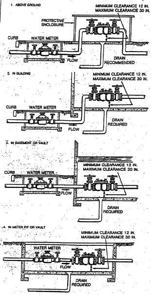
Yes, backflow prevention assemblies should be installed in accordance with the manufacturer’s installation instructions, the Uniform Statewide Building Code and any additional instructions offered by the Public Utility Division. RPP devices are installed in a horizontal position with the relief port down. They should not be installed in a pit or in any location that could experience flooding, as their functionality is impacted by submersion in fluids. To allow for easy access and maintenance, RPP devices should be installed at least 12 inches above the floor with 24-inch clearance on all sides, and should be in a location safe from freezing temperatures and vandalism. The leaking action of the relief valve should also be considered (installation above a floor drain is ideal).
Unlike RPPs, DCVAs can be installed in a pit and can be submerged but must still be protected against freezing and vandalism. Like the RPP, it should be installed horizontally and in an area that is easily accessible and with plenty of clearance for the maintenance professional to inspect and test the device.
A PVB should be installed in an easily accessible area that is at least twelve inches above the highest downstream outlet (this is necessary thanks to the PVB’s vulnerability to backpressure), and like the other devices must be protected from freezing and vandalism. The air-inlet port must never be blocked or sealed as this defeats the usefulness of the device.
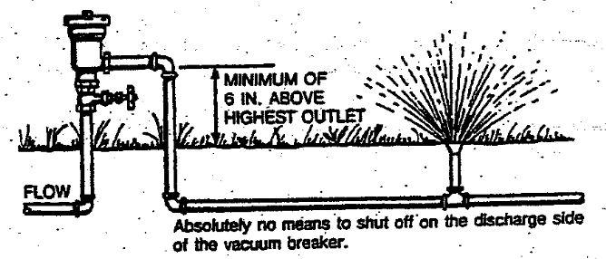
Finally, Atmospheric Vacuum Breakers (AVBs) must be installed 6 inches above the highest point of downstream outlet, the highest point of downstream usage, the highest downstream piping, and the highest flood elevation. AVBs must be installed downstream of all valves and pumps (aspirators can be used downstream of AVBs). Like all other devices, the AVB must be kept safe from freezing temperatures and vandals, and like the PVB the assembly’s air inlet port should never be blocked or sealed. Figures 4, 5, 6, and 7 display the optimal placement of the various backflow prevention assemblies.
Figure 4 – RPP placement guide (all images from AWWA) Figure 5 – DCVA placement guide
Figure 6 – AVB placement guide Figure 7 – PVB Placement guide
-
Backflow Prevention
A Plumbing permit is not required to install a backflow device, unless its installation requires disturbing city property in a manner that would require a plumbing permit. In the majority of cases it is not necessary, however.
-
Backflow Prevention
An approved Plumbing Permit is required to remove a backflow prevention device that is currently in operation. The Director of Public Works & Utilities is authorized to take whatever steps are necessary to protect the City’s water supply in the event of an unauthorized removal of a backflow prevention device.
-
Backflow Prevention
Backflow prevention devices must be tested at least annually. Backflow assemblies are mechanical assemblies and as such they are subject to fail, which is why the VDH requires that they be tested at least once a year. Newly installed backflow assemblies and backflow assemblies that are repaired or relocated must also be tested. This requirement is echoed by the Virginia Maintenance Code, International Plumbing Code, and the Environmental Protection Agency’s Cross Connection Control Manual. Only certified individuals may perform inspections and tests of backflow prevention assemblies – see here.
-
Backflow Prevention
Though the Division of Public Utilities monitors the installation and maintenance of these assemblies as required by the VDH, the City of Petersburg does not have any influence or control over the contractor’s pricing, and it can vary from one testing contractor to another. Currently the prices range from $85 to $200. Group pricing, whether through a neighborhood or homeowner’s association is an option that may lower your annual testing cost. Combining the test with other irrigation system maintenance may also net a savings for the homeowner.
The City of Petersburg Division of Public Utilities does not endorse, guarantee, or warrant any work performed by the testing contractors. All interactions between customers and contractors are private transaction between these two entities.
-
Backflow Prevention
Per the Virginia Administrative Code 12VAC5-590-630, in order to be certified to inspect and test a backflow prevention assembly, an individual must apply here to take the examination to be a backflow prevention device worker. They must also have documentation showing that their test kit has been calibrated within the last year.
-
Backflow Prevention
Yes, the City tracks the backflow assembly information in our data base which will generate a reminder letter to our customers reminding them when their annual test is due. You should receive a reminder letter 30 to 45 days before your test is due. If you do not receive a letter, please contact the Program Coordinator at 804-835-0928 or hwingfield@petersburg-va.org.
-
Backflow Prevention
The absence of a reminder letter does not void the requirement of the annual inspection required by the Division of Public Utilities. There is general information (including this F.A.Q.) and a copy of a blank test form on the City’s website. If you have not received a letter, please contact the Program Coordinator at 804-835-0928 or hwingfield@petersburg-va.org and provide him with the information necessary so we can send you the annual testing notifications.
-
Backflow Prevention
The completed test form must be submitted to the City’s Division of Public Utilities either via email to hwingfield@petersburg-va.org or hand-delivered or mailed to:
City of Petersburg Division of Public Utilites
C/O Hall Wingfield
1340 E Washington Street
Petersburg, VA 23803Please retain a copy of the test form for your records as required by the City Code of Petersburg and state law.
-
Backflow Prevention
AVB – Atmospheric Vacuum Breaker
AWWA – American Water Works Association
DCVA – Double Check Valve Assembly
PVB – Pressure Vacuum Breaker
RPP – Reduced Pressure Principle Device
VDH – Virginia Department of Health